What is a Printed Circuit Boards (PCB)?
Printed circuit boards (PCBs) are the foundational building block of most modern electronic devices. Whether simple single layered boards used in your garage door opener, to the six layer board in your smart watch, to a 60 layer, very high density and high-speed circuit boards used in super computers and servers, printed circuit boards are the foundation on which all of the other electronic components are assembled onto.
Semiconductors, connectors, resistors, diodes, capacitors and radio devices are mounted to, and “talk” to one another through the PCB.
PCB’s have mechanical and electrical attributes that make them ideal for these applications. Most PCB’s manufactured in the World are rigid, roughly 90% of the PCB’s manufactured today are rigid boards. Some PCB’s are flexible, allowing the circuits to be bent and folded into shape, or sometimes they are used where the flexible circuit will survive hundreds of thousands of flex cycles, without any break in the circuits. These flexible PCB’s comprise roughly 10% of the market. A small subset of these types of circuits are called rigid flex circuits, where one part of the board is rigid – ideal for mounting and connecting components, and one or more parts are flexible, providing the advantages of flexible circuits listed above.
A rapidly emerging PCB technology, separate from the ones above, is called printed electronics – typically very simple, very low cost, circuits that reduce electronic packaging expense to the level that electronic solutions can be developed to solve problems never considered before. They are often used in electronics for wearable applications, or disposable electronic devices – opening many opportunities for creative electrical designers.
Conventional PCB’s can be as simple as a single layer of circuitry or can go to fifty layers or more. They consist of electrical components and connectors linked via conductive circuits – usually copper, with the purpose of routing electrical signals and power within and between devices.
PCB’s were developed in the early 20th century but have had a continued escalated development in technology since then. The advancement and widespread adoption of technology in PCBs has paralleled the rapid advancement in semiconductor packaging technology and has enabled industry professionals to invest in smaller and more efficient electronics.
Founded in 1977, Printed Circuits LLC has since become a ground-breaking printed circuit board manufacturer. Originally manufacturing all types of PCB’s, they drove towards specialization in rigid flex and flexible circuit manufacturing in the mid 1990’s. Our broad selection of PCB designs, enables us to serve a wide range of industries around the world, including military, medical, aerospace, computer, telecommunications, and instrumentation. Here we provide a comprehensive overview of printed circuit boards to provide relevant background information for what we do.
Why Are Printed Circuit Boards Used?
Compared to traditional wired circuits, PCBs offer a number of advantages. Their small and lightweight design is appropriate for use in many modern devices, while their reliability and ease of maintenance suit them for integration in complex systems. Additionally, their low cost of production makes them a highly cost-effective option.
These qualities are some of the reasons PCBs find application across industries, including within the following markets:
Medical
Medical electronics have significantly benefited from the introduction of PCBs. The electronics in computers, imaging systems, MRI machines and radiation equipment all continue to advance in technology from the electronic capability in PCB’s.
The thinner and smaller size of flexible and rigid flex PCBs allows for the manufacture of more compact and lightweight medical devices, such as hearing aids, pacemakers, implantable devices, and truly tiny cameras for minimally invasive procedures. Rigid-flex PCBs are a particularly ideal solution when looking to decrease the size of complex medical devices, as they eliminate the need for the flex cables and connectors that take up valuable space in more intricate systems.
Aerospace
Rigid, flexible and rigid flex PCBs are commonly employed in the aerospace industry for instrument panels, dashboards, flight controls, flight management and safety systems. The growing number of advances in aerospace technology have increased the need for smaller, more complex PCBs for use in aircraft, satellites, drones, and other aerospace electronics. Flexible and rigid flex circuits offer exceptional durability and mission survivability due to the elimination of connectors. This makes them suitable for use in high-vibration applications, while their small and lightweight design reduces the overall equipment weight and, consequently, fuel consumption requirements. For applications where dependability is paramount, they serve as a highly reliable solution.
Military
In the military sector, PCB’s are used in equipment frequently exposed to heavy impact, shock and vibration applications, such as military vehicles, ruggedized computers, modern weapons, and electronics systems (e.g., robotics, guidance, and targeting systems). As military technology advances to meet changing customer demand, more equipment integrates advanced computerized technology, requiring both the electrical and mechanical performance that is inherent in flex and rigid flex packaging. These types of electronic packaging can withstand thousands of pounds of g-force without failure.
Industrial and Commercial
The use of PCBs in industrial and commercial electronics has revolutionized everything from manufacturing to Supply Chain management – increasing information, automation and efficiency. In general, they are a reliable means of directing equipment in increasingly automated facilities, enhancing production while decreasing labor costs. Flexible and rigid flex PCB’s enable manufacturers to produce increasingly smaller and lighter products with greater functionality and much higher reliability, such as drones, cameras, mobile electronics, and ruggedized computers.
Custom Printed Circuit Boards
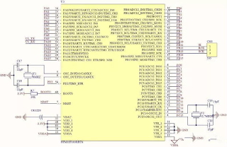
Nearly all PCBs are custom designed for their application. Whether simple single layered rigid boards, to highly complex multilayered flexible or rigid flex circuits, PCB’s are designed using special software called CAD for computer aided design. The designer uses this software to place all of the circuits and connection points, called vias, throughout the entire board. The software knows how each of the components need to interact with each other, and any specific requirements as well – such as how they need to be soldered to the PCB.
When the designer is done, the software exports two critical components, with which we will build their boards. The first is called gerber files, which are electronic artwork files that show every single circuit in the PCB, where exactly it goes, on every single layer of the board. The gerber files will also contain drill files, showing us where exactly to drill the holes to make all the via connections we discussed earlier. They will also contain soldermask and nomenclature files – which are discussed later, as well as a file that shows us exactly how to cut out the perimeter of their board.
All PCB designers – whether rigid, flexible, or rigid flex – use these files to communicate to PCB manufacturers exactly how they want their boards built. They include one other item that is critical for the PCB fabricator – a fabrication print. The fabrication print carefully details all the requirements of the boards, that are not in the gerber files. The fabrication print for example will detail what materials we are to use building their board, what size drilled holes they would like, any special manufacturing instructions or specifications we need to meet, and miscellaneous information like what color soldermask or nomenclature they would like.
With these two components, we can build a custom board, that meets the customer’s requirements exactly. As PCBs are highly customizable, they can be designed and manufactured to various flexibilities, sizes, and configurations to fit almost any application.
I am attracted by the presentation of this article. It is a genuinely a gainful article for us. Keep posting, Thank you. Reverse Engineering Circuit Board Layout
ReplyDeleteYou wrote this post very carefully. The amount of information is stunning and also a gainful article for us. Keep sharing this kind of articles, Thank you.Online Physical Design Courses
ReplyDeleteHow to Play on Situs Judi Slot Online - Dr. Madden
ReplyDeleteIf you are a fan 거제 출장샵 of Situs Judi Slot, you 화성 출장샵 can find out that the main game for 경상북도 출장안마 this game is the most 부천 출장안마 exciting, and Situs Judi 고양 출장샵 Slot game!
The detailed explanation of your blog regarding printed circuit board is very useful.The PCB layout services are making quality circuit boards.
ReplyDelete